Rvs have a battery bank which is used to power the rv appliances. Moreover, there is another benefit of soft ferrite cores, that is, they can change the magnetic.
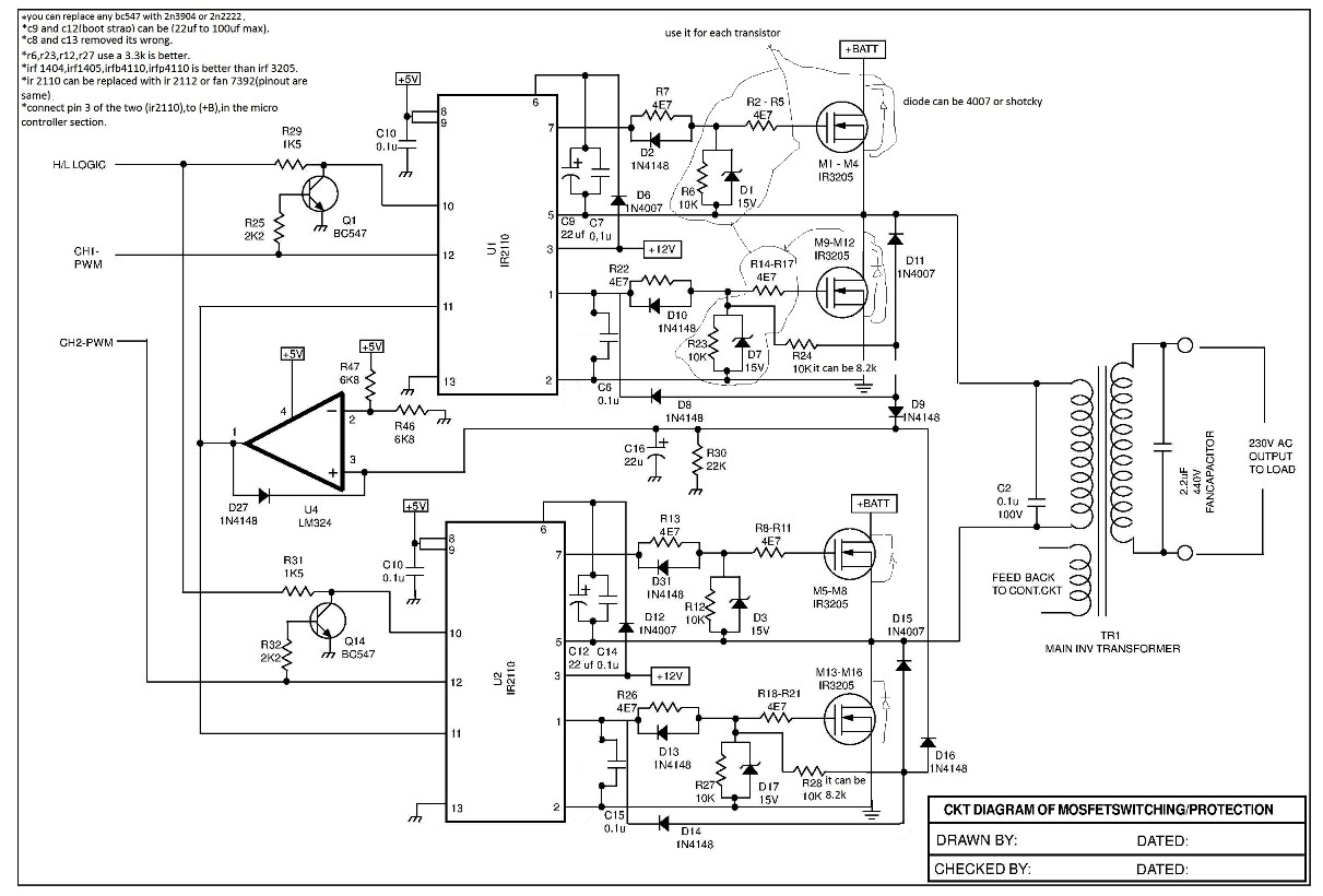
Ferrite Core Inverter Circuit Diagram. In this video, i�ll show you circuit diagram of my smps (switch mode power supply) based inverter and explain it. 5kva ferrite core inverter circuit preparation details:
 PWM Inverter Using IC TL494 Circuit Homemade Circuit From homemade-circuits.com
But only few of them I meant sinewave inverter without a charging unit,a simple one. 7 simple inverter circuits you can build at home homemade circuit projects.
PWM Inverter Using IC TL494 Circuit Homemade Circuit
5kva ferrite core inverter circuit full working diagram with. We will learn how a ferrite core inverter functions stage by stage extensively. The ferrite core comes up with basic two types, hard ferrite core, and soft ferrite core. I meant sinewave inverter without a charging unit,a simple one.
 Source: homemade-circuits.com
You �ll see it, working with batteries and. This 100 watt compact ferrite inverter is just like other like inverter circuits but is. Inverter connection to db help needed inverters power forum renewable energy discussion. The ferrite core comes up with basic two types, hard ferrite core, and soft ferrite core. Dc/ac pure sine wave inverter jim doucet dan eggleston.
 Source: homemade-circuits.com
Egs002 sinusoid inverter driver board user manual 1 description 2 circuit schematic. 100 watt compact ferrite inverter circuit. Inverter operation using asic eg8010. Dc/ac pure sine wave inverter jim doucet dan eggleston jeremy shaw mqp terms abc 20062007 advisor: 220 volt ac output sinus inverter circuit built on sg3525 smps control integrator transformer used in transformer computer power supply (ferrite.
 Source: homemade-circuits.com
Total voltage = 60v actual voltage = 66v fullcharge(13.2v each batt)voltage = 69v trickle level charge voltage. A very small and compact ferrite based 100 watt inverter circuit can be built using around the ic 4047 which has an internal oscilator. Inverter connection to db help needed inverters power forum renewable energy discussion. 5kva ferrite core inverter circuit full working.


